English
 中文简体
中文简体 русский
CF32 Hydraulic Clamping CNC Polygon Turning Machine
Cat:Small Polygon Lathe
CF32 hydraulic clamping CNC polygon lathe is designed for milling small and medium-sized high-precision parts, which can mill square, octagonal, hexag...
See Details
The Machine Frame and Table
The frame is the foundation of a CNC milling machine factory, providing structural stability and support for all other components. It is typically made from cast iron or steel to ensure rigidity and minimize vibration during operation. A stable frame is essential for maintaining precision, as any movement or flex can affect the accuracy of the cut.
The table, mounted on the frame, supports the workpiece during milling. It can move in different directions, usually along the X, Y, and Z axes, depending on the type of milling machine. The table may also include fixtures, clamps, or vices to hold the workpiece securely. Precise movement of the table allows the cutting tool to reach the desired locations on the material, ensuring accurate shaping and dimension control. The frame and table together create the foundation for stable and controlled milling operations.
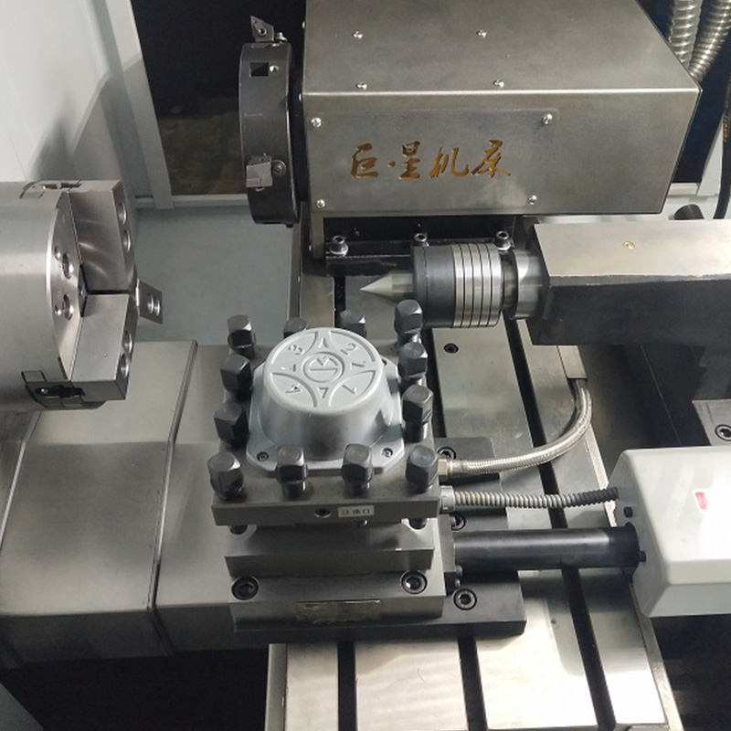
The Spindle and Cutting Tool
The spindle is the rotating component that holds the cutting tool and provides the necessary speed and torque for material removal. It can move along specific axes to position the tool accurately relative to the workpiece. The spindle may be equipped with a motor or drive system capable of varying rotational speeds, depending on the material and type of milling operation.
The cutting tool itself comes in various shapes, such as end mills, drills, or face mills, depending on the milling task. Each tool is designed to perform specific operations, including cutting, shaping, drilling, or finishing surfaces. The spindle and cutting tool work together to remove material efficiently, producing precise features according to the programmed design. The combination of spindle speed, feed rate, and tool type determines the quality of the finished part.
CNC Control System
The CNC control system is the brain of the milling machine. It interprets the programmed instructions, often written in G-code, and translates them into precise movements of the spindle, table, and other components. The control system manages positioning, speed, feed rate, and tool changes, ensuring the milling operation follows the desired specifications.
Modern CNC systems include touchscreens or monitors that allow operators to input commands, monitor performance, and adjust parameters. Some systems can store multiple programs, making it possible to produce different parts without extensive reprogramming. The control system is essential for automation, reducing human error, and improving consistency in production. It enables complex milling operations that would be difficult or impossible to achieve manually.
Feed Mechanism and Drive Components
The feed mechanism includes motors, lead screws, ball screws, and linear guides that move the table, spindle, and other components along their respective axes. These drive components convert rotary motion from the motors into precise linear movement, allowing accurate positioning of the workpiece relative to the cutting tool.
The feed mechanism ensures smooth, controlled motion and can adjust speed and acceleration according to the requirements of the milling operation. High-quality drive systems reduce backlash and maintain precision, which is critical for producing accurate parts. In addition to moving the table and spindle, some CNC milling machines include automatic tool changers, coolant systems, and sensors, which rely on the feed and drive components to function correctly. These mechanisms support consistent operation and extend the life of both the machine and the tools.
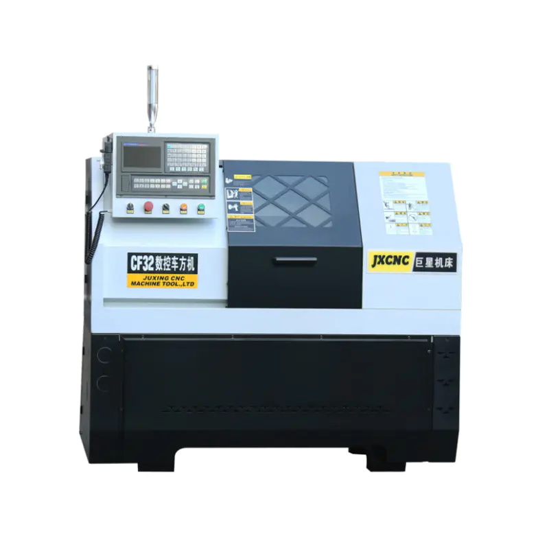
CF32 hydraulic clamping CNC polygon lathe is designed for milling small and medium-sized high-precision parts, which can mill square, octagonal, hexag...
See Details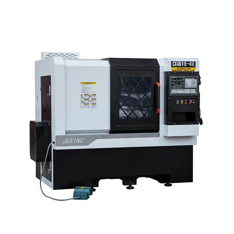
The CX40 High Precision Linear Track Horizontal CNC Lathe Machine is designed to provide exceptional performance and versatility for precision machini...
See Details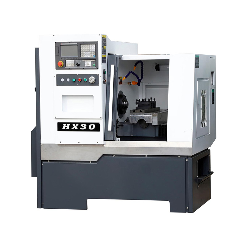
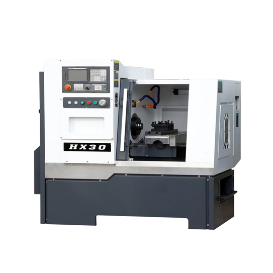
A notable feature of the HX30 Mandrel Bar Feeder Cheap CNC Lathe is its efficient and reliable mandrel bar feeder. The mandrel serves as a support for...
See Details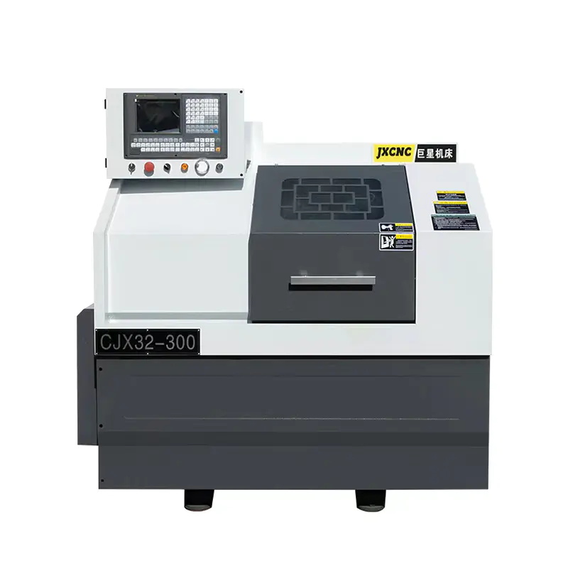
The JX32-300 Mini Economical CNC Lathe Machine is designed to provide high precision and efficient machining for a wide range of metal products. With ...
See Details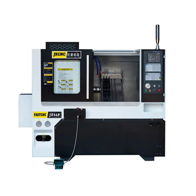
The JX46P Slant Bed CNC Lathe Machine of Cast Iron Machine Base is a high-performance machine tool designed for various machining operations. With its...
See Details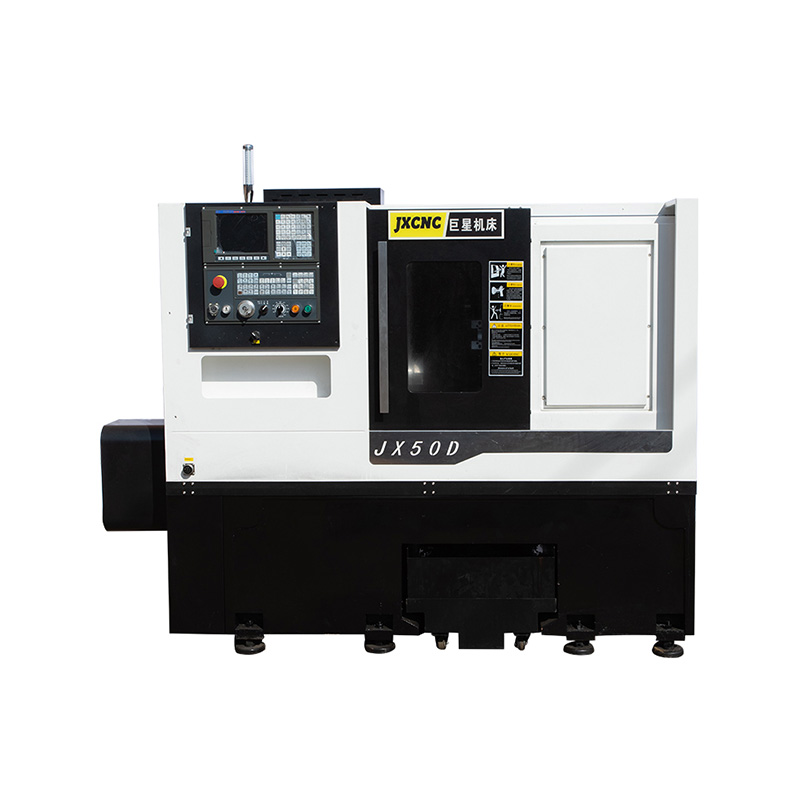
Introducing the JX50D CNC Machine Tools List from China's CNC machine tools manufacturer. Our machine tools are equipped with a servo hydraulic turret...
See Details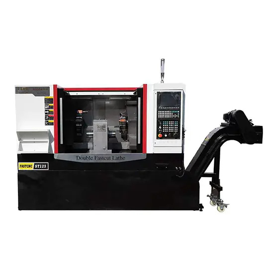
The JX125 Double Head CNC Machine is a cutting-edge machine tool that utilizes a central spindle, two Z-axes, two X-axes, and bidirectional drag plate...
See Details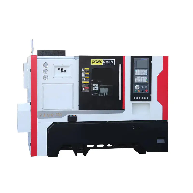
The JX52D Machine Tool CNC Lathe is specifically designed for lathe every kinds of material with precision and efficiency. It is equipped with advance...
See DetailsTEL : +86-576-87491531
FAX : +86-576-87493038
E-MAIL : chinajuxing@aliyun.com
ADDRESS: Longxi Industrial Zone, Yuhuan City, Taizhou City, Zhejiang Province, China
CopyrightTaizhou Yestar Intelligent Equipment Co., Ltd. All Rights Reserved.