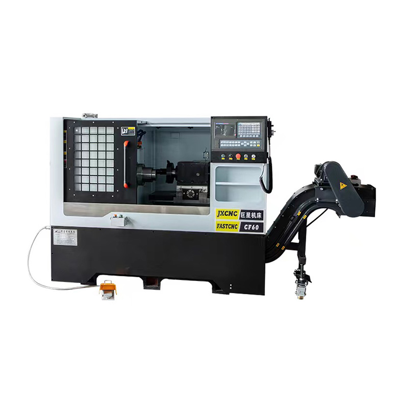
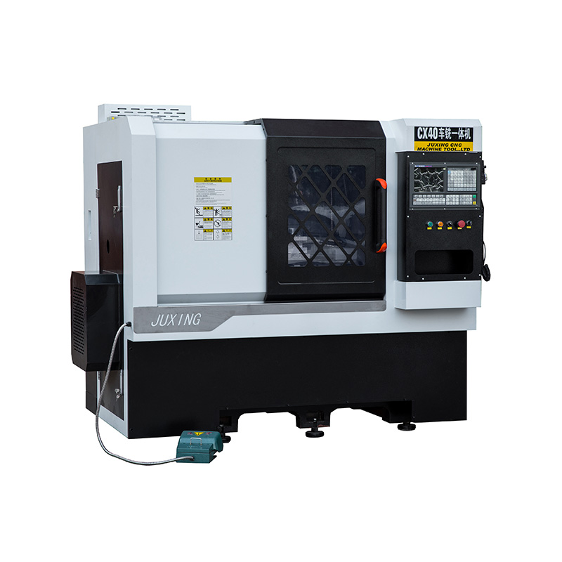
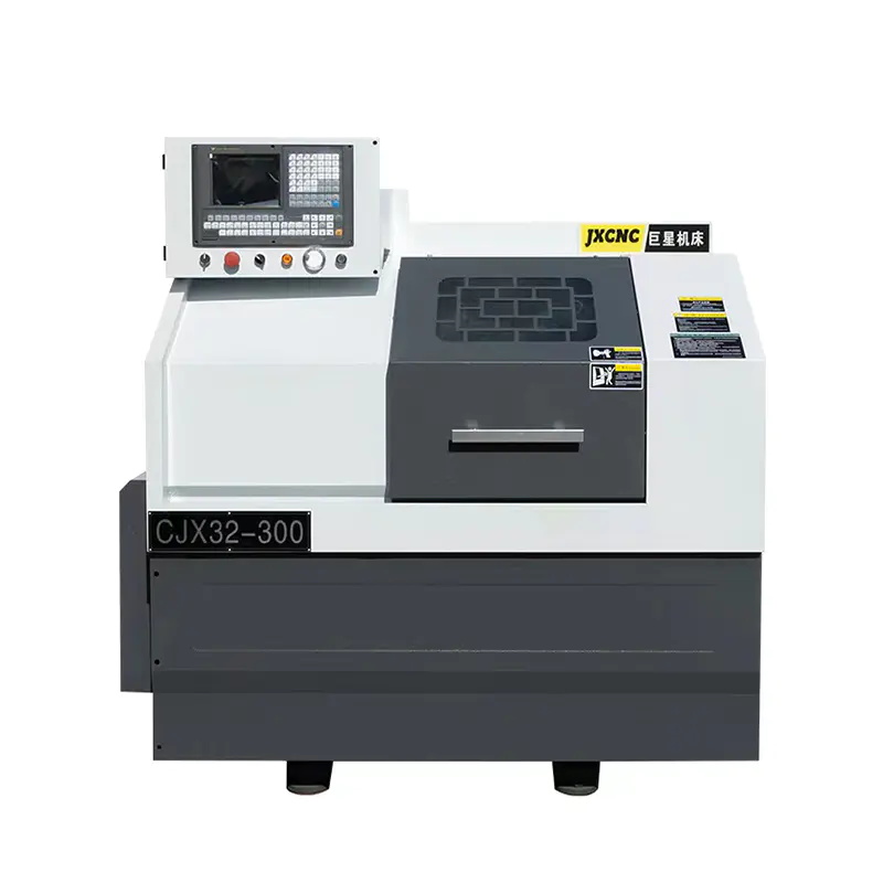
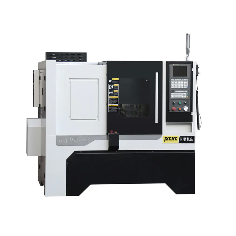
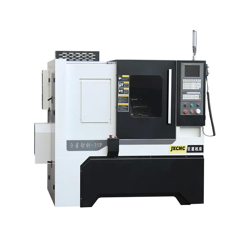
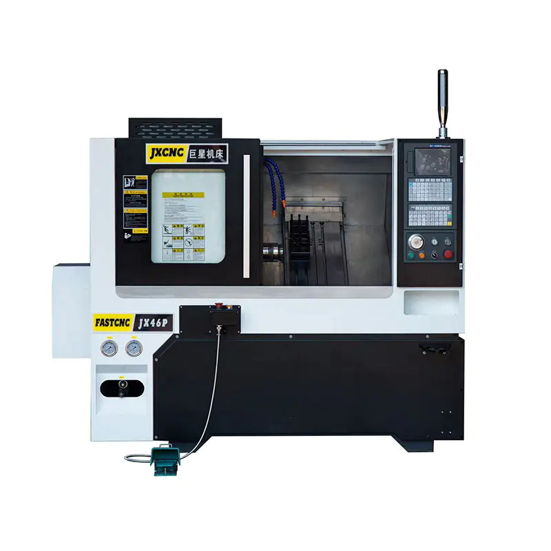
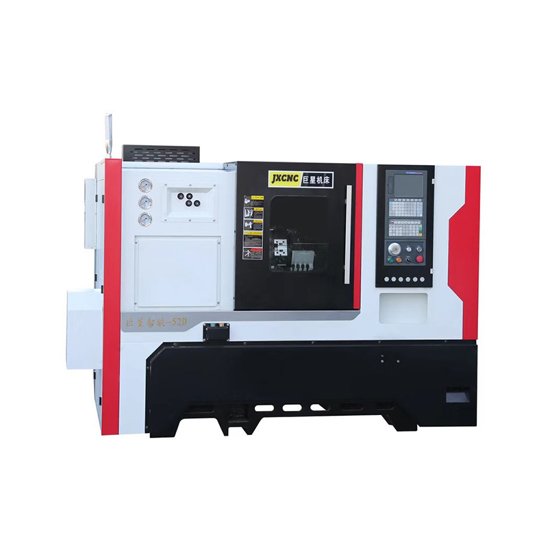
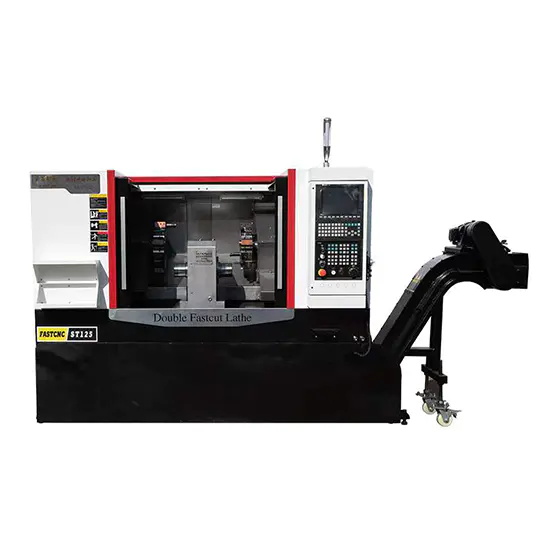
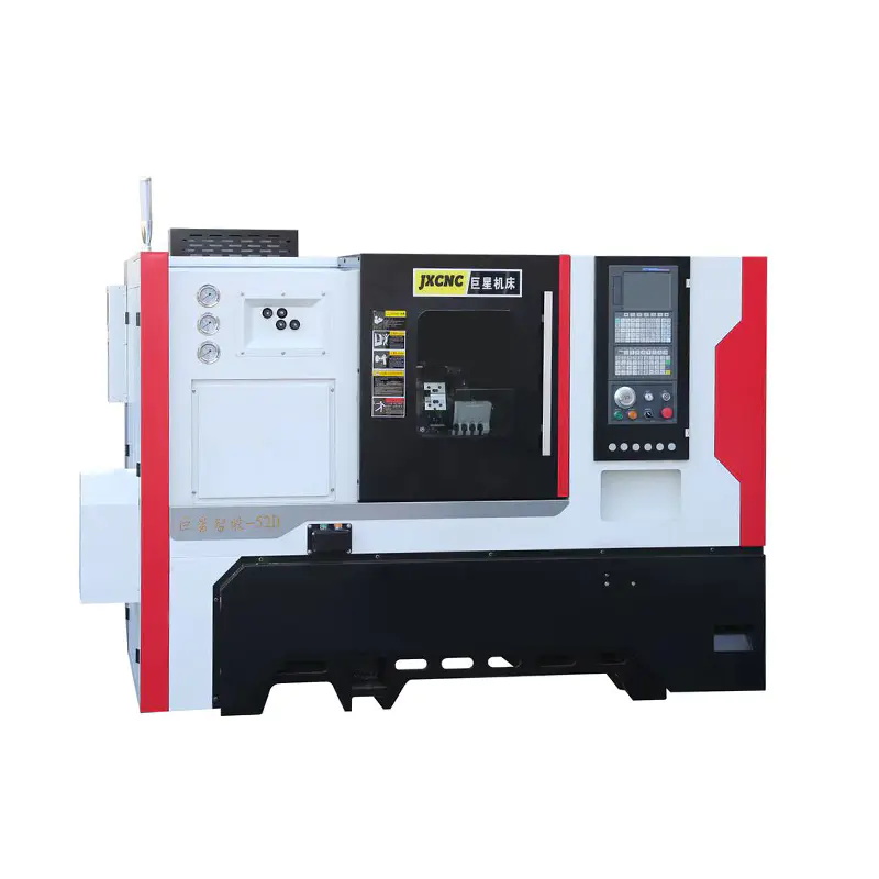
Linear guideways have become a common configuration on modern slant bed CNC lathes, but their role involves more than allowing the carriage to move quickly. Guideway design affects how the machine responds to cutting forces, positioning commands, vibration, and repeated machining cycles. This makes the relationship between linear guides and structural rigidity worth examining before investing in a CNC Slant Bed Lathe with Linear Guide.
Machine rigidity does not come from the guideway alone. Bed geometry, casting structure, ball screws, spindle support, carriage design, and guideway arrangement all contribute to the overall mechanical behavior.
What Do Linear Guides Actually Change?
Linear guideways normally use rolling elements between the rail and carriage. Compared with traditional sliding or box ways, this arrangement can provide smooth movement with relatively low friction and responsive axis motion.
- Low-friction movement: Helps the X and Z axes respond smoothly to CNC commands.
- Rapid positioning: Supports fast traverse movements between machining positions.
- Repeatable motion: Helps maintain consistent axis positioning during repeated cycles.
- Compact installation: Allows manufacturers to design relatively streamlined carriage systems.
Current slant-bed machines illustrate the range of specifications available. One 45-degree model uses linear guides designated Z35 and X30, with rapid X and Z feeds of 18 m/min and positioning accuracy of 0.016 mm.
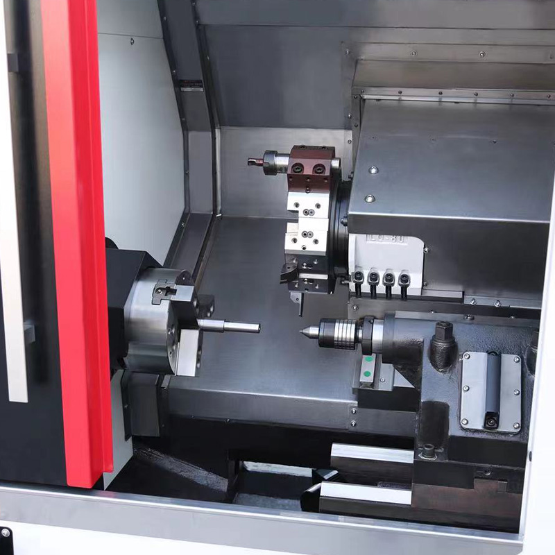
Does a Linear Guide Mean Less Rigidity?
Not necessarily. Rigidity is determined by the complete mechanical structure rather than the guideway type alone. A well-designed CNC Slant Bed Lathe with Linear Guide can combine rolling guideways with a rigid cast bed, wide rail spacing, properly supported ball screws, and a stable spindle assembly.
The inclined bed itself also contributes to the structural arrangement. Commercial machines commonly use 30°, 45°, or similar slant angles. A 45-degree design, for example, can provide a substantial inclined support surface for the carriage and tooling area.
Rigidity Comes from Several Areas
- Bed casting: Provides the foundation for the spindle and axis systems.
- Guideway spacing: Wider support can help distribute cutting loads across the carriage.
- Ball screw support: Proper bearing arrangements help maintain controlled axis movement.
- Spindle structure: A rigid spindle assembly is essential during interrupted and heavy cuts.
- Turret connection: Tool clamping and turret stiffness affect how cutting forces reach the machine structure.
Rapid Movement Is Only Part of the Story
High traverse speed can look attractive on a specification sheet, but machining performance also depends on what happens during actual cutting. A tool generating radial or axial cutting forces transfers those loads through the turret, carriage, guideways, bed, and spindle structure.
That is why a CNC Slant Bed Lathe with Linear Guide should not be judged by rapid-feed figures alone. A machine may offer 20–30 m/min rapid movement while still requiring a carefully engineered bed and guideway arrangement to maintain stability during cutting.
Takisawa's NEX-106, for example, combines heavy-duty linear slideways with a cast-iron structure and a 12-station servo turret. Its listed rapid traverse rates reach 24 m/min on X and 30 m/min on Z, while spindle speed reaches 5,000 rpm.
Small Parts and Heavy Cuts Need Different Priorities
The appropriate guideway configuration depends partly on the component family. Precision-oriented production involving smaller or medium-sized parts can benefit from the responsive motion characteristics of linear guides. Heavy roughing applications place greater emphasis on load capacity, vibration control, and structural support.
- Precision shafts: Smooth axis response and repeatable positioning can be valuable.
- Automotive components: Linear guides can support rapid tool movement across repetitive machining cycles.
- Small hydraulic parts: Compact guideway arrangements can suit frequent turning and drilling operations.
- Heavy roughing: Bed width, carriage support, spindle power, and guideway load capacity deserve closer attention.
Some manufacturers also offer a choice between linear guideways and box ways. Force One, for example, lists both options for its FCL series, while its Y-axis configuration uses roller-type linear guideways.
Which Specifications Deserve a Closer Look?
Comparing guideways requires more than checking whether the specification sheet says “linear.” Several related figures provide a clearer picture of the machine's mechanical design.
- Guide rail size: Larger rail dimensions can indicate greater load capacity, depending on the complete design.
- Axis travel: Check X and Z travel against the actual component envelope.
- Rapid traverse: Useful for understanding positioning capability, but not a direct measurement of cutting rigidity.
- Positioning accuracy: Indicates how precisely the axis can reach programmed coordinates.
- Repeatability: Shows how consistently the axis can return to a commanded position.
The Better Question Is Not Linear or Rigid
Linear guides and rigidity should not automatically be treated as opposing concepts. A properly engineered CNC Slant Bed Lathe with Linear Guide can combine low-friction axis movement with a substantial slant-bed structure. The actual machining result depends on how the guideways, bed, spindle, screws, turret, and control system work together.
For buyers comparing CNC turning equipment, the useful approach is to match guideway design with the intended part size, material, cutting depth, tooling strategy, spindle characteristics, and required tolerances. Looking beyond a single “linear guide” label can reveal much more about what a slant-bed CNC lathe is designed to handle.



 English
 中文简体
中文简体 русский