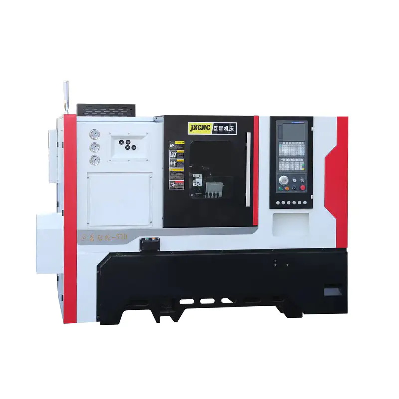
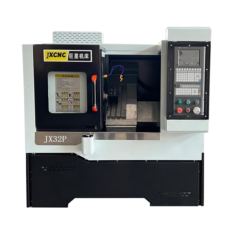
Precision machining often focuses on spindle quality, tooling condition, and programming strategy. A less visible contributor sits inside the motion system itself: linear guide performance. A Linear Guide CNC Machine depends on guideways, preload settings, lubrication stability, and structural stiffness to maintain repeatable motion. Once any of these elements drift out of ideal condition, machining errors may appear without obvious warning signs.
Industry studies and field reports show that axis transmission faults, guideway wear, and friction instability are among the core reasons CNC systems lose accuracy over time, even when control systems still report correct positioning feedback. The result is a subtle deviation that does not immediately trigger alarms but gradually impacts surface quality and dimensional consistency.
1. Stick-Slip Motion Creates Inconsistent Tool Path Behavior
Linear guide systems rely on smooth rolling or sliding contact. Wear, contamination, or insufficient lubrication introduces irregular friction known as stick-slip behavior.
This condition causes:
- Micro jerks during axis movement
- Slight delay in axis response under load
- Non-uniform feed motion during finishing passes
Surface symptoms often include faint banding or irregular tool marks that appear even after tool changes. Because CNC controllers assume ideal motion, these variations remain “invisible” until part inspection.
Stick-slip becomes more noticeable at low feed rates, especially during finishing operations where motion smoothness is critical.
2. Preload Imbalance Alters Axis Stability
Linear guides are assembled with preload to eliminate clearance and improve rigidity. However, uneven preload distribution can create unexpected motion characteristics.
Common consequences:
- One axis resists movement more than the opposite direction
- Slight axis tilt under cutting load
- Reduced repeatability during rapid direction changes
A machining center may still achieve correct absolute positioning, yet fail to return to identical micro-locations repeatedly. This mismatch often appears as inconsistent surface finish between identical parts.
A recent technical analysis of CNC machining centers highlights that repeatability degradation is strongly linked to transmission system stability and backlash compensation limits .
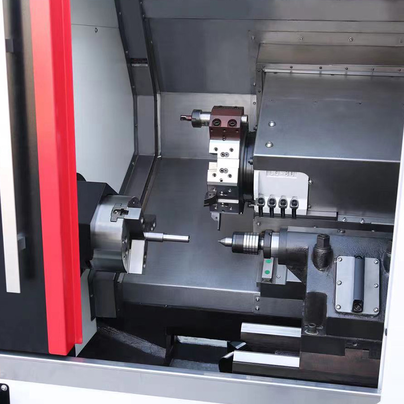
3. Guideway Wear Generates Subtle Geometric Drift
Wear on linear guides does not occur evenly. Contact zones develop localized polishing, pitting, or micro deformation over long production cycles.
Effects include:
- Gradual axis droop over travel distance
- Slight angular deviation in tool path
- Uneven load distribution across carriage blocks
In long-axis machining, this may present as taper errors or surface waviness that changes depending on tool position on the table. Operators often misinterpret this as tooling or CAM issues, while the root cause remains mechanical degradation inside the guide system.
Once wear reaches a certain level, even compensation tables in CNC controllers cannot fully correct the resulting geometry distortion.
4. Vibration Transfer Through Guide Structure
Linear guide systems also act as transmission paths for vibration. Cutting forces, spindle imbalance, or external environmental disturbances can propagate through the machine frame.
Typical vibration sources:
- Imbalanced spindle rotation
- Intermittent cutting loads
- Nearby industrial equipment
- Resonance between axis movement frequency and structural modes
Once vibration couples into the guideway system, it can amplify into chatter marks on the workpiece surface. Studies on machining stability show that resonance between cutting frequency and structural natural frequency is a major trigger for surface ripple formation.
This explains why identical programs may produce different surface quality depending on machine load or time of day.
5. Lubrication Instability Changes Friction Profile
Guideways require stable lubrication film thickness. Variations in oil supply or contamination alter the contact condition between rolling elements and raceways.
Observed machining effects:
- Sudden change in surface finish quality during long runs
- Increased axis noise during direction reversal
- Irregular cutting depth consistency
Even small inconsistencies in lubrication pressure can shift friction behavior from smooth rolling to partial sliding, introducing unpredictable motion variation.
Over time, this leads to inconsistent chip thickness during finishing operations, especially in aluminum and stainless steel machining.
6. Servo Response Masks Mechanical Weakness
Modern CNC control systems often compensate for minor mechanical issues through servo tuning and encoder feedback. However, compensation has limits.
A machine may still:
- Reach commanded coordinates accurately
- Fail to maintain micro-stability under load
- Produce inconsistent surface texture despite correct geometry
This mismatch is why hidden machining errors are difficult to diagnose. The system “looks correct” in diagnostics while physical motion quality degrades under real cutting forces.
Once dynamic instability develops, increasing feedrate or changing tool geometry may temporarily mask symptoms but not eliminate the underlying cause.
7. Load Distribution Differences Across Axis Travel
Linear guide systems do not experience uniform loading across the entire stroke. Certain zones of travel carry heavier structural stress due to:
- Machine base geometry
- Workpiece positioning
- Overhang tool load variations
This leads to location-dependent machining variation. Parts machined at one side of the table may show different surface quality compared to those machined at the center.
Such variation is often interpreted as programming inconsistency, though it originates from mechanical stiffness variation along the guide path.
Practical Takeaway
A Linear Guide CNC Machine can maintain good nominal accuracy while still producing hidden machining errors. These errors usually come from:
- Friction instability in guideways
- Preload imbalance
- Wear-induced geometric drift
- Vibration transmission through the structure
- Lubrication inconsistency
- Servo compensation masking mechanical weakness
- Uneven load distribution across travel range
The key challenge is that these issues do not always show up in basic calibration checks. They emerge only during real cutting conditions, especially in finishing operations where dynamic stability becomes critical.

 English
 中文简体
中文简体 русский