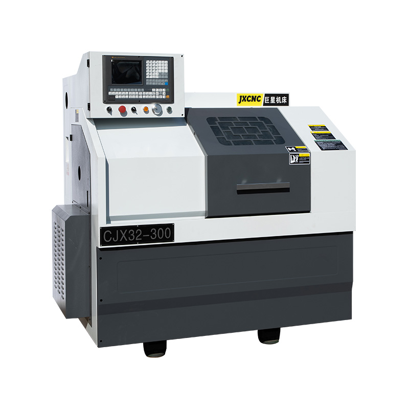
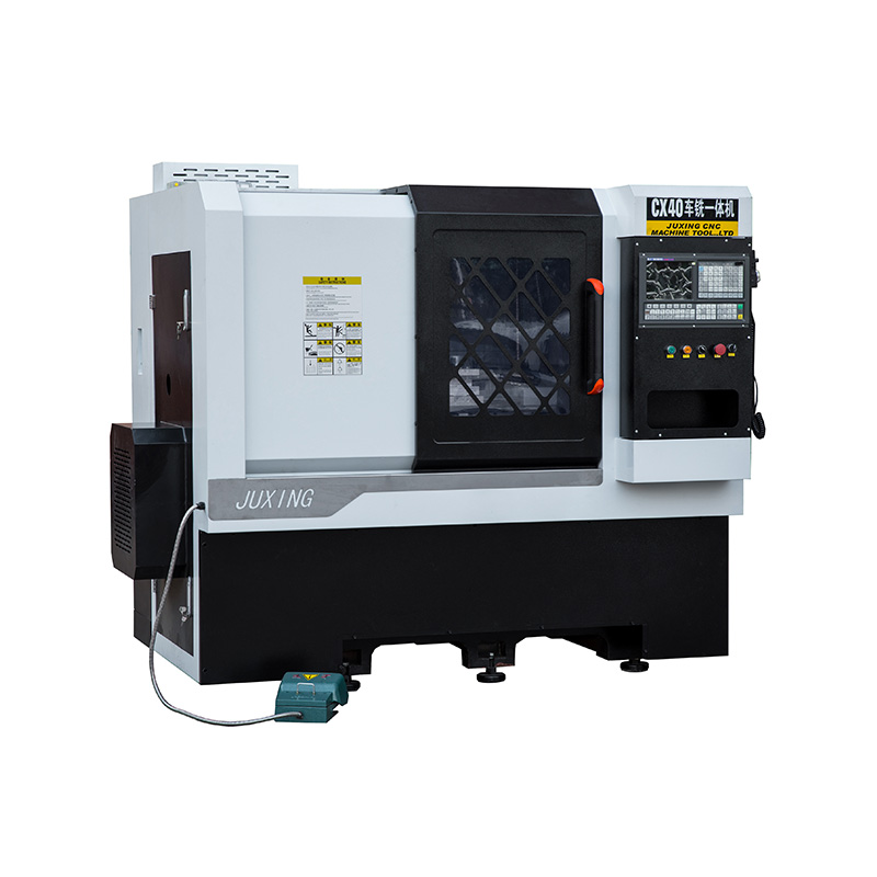
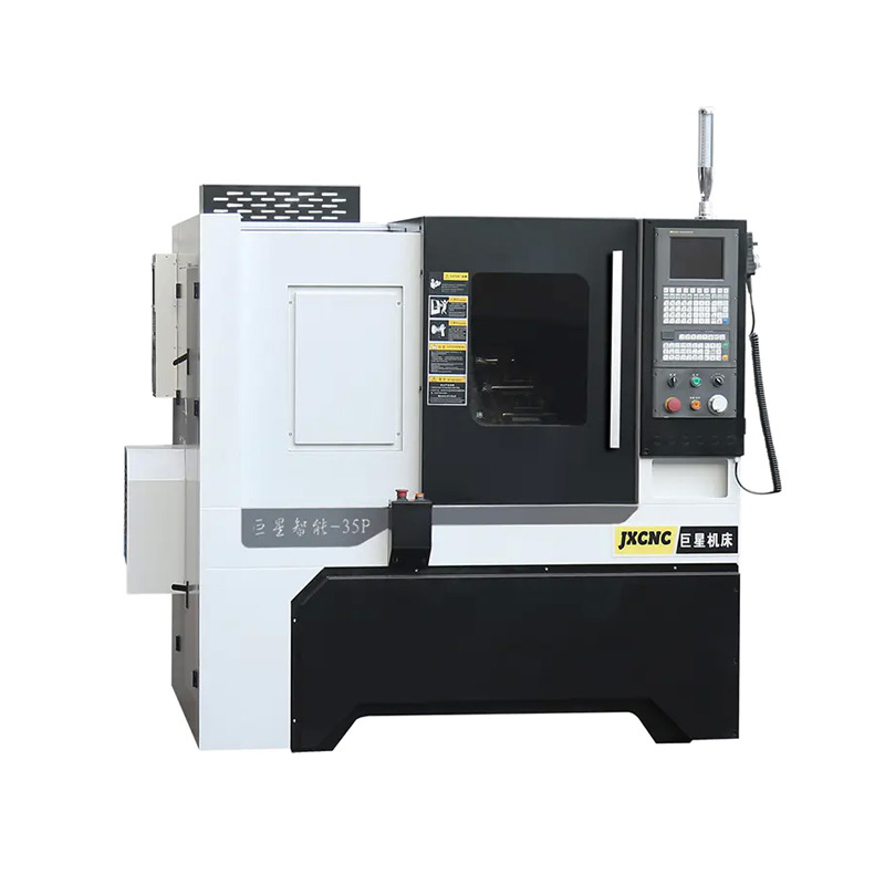
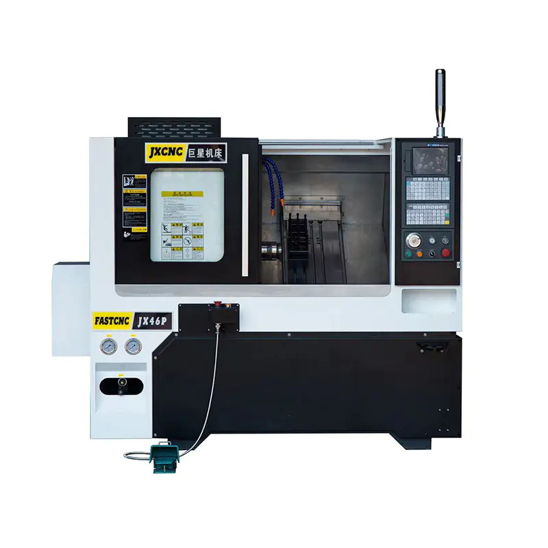
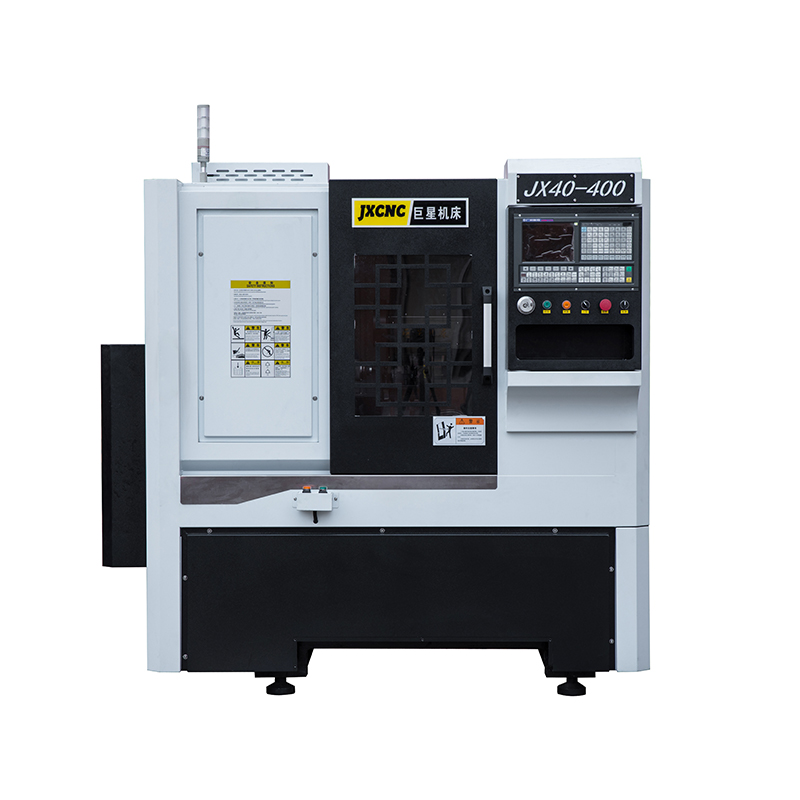
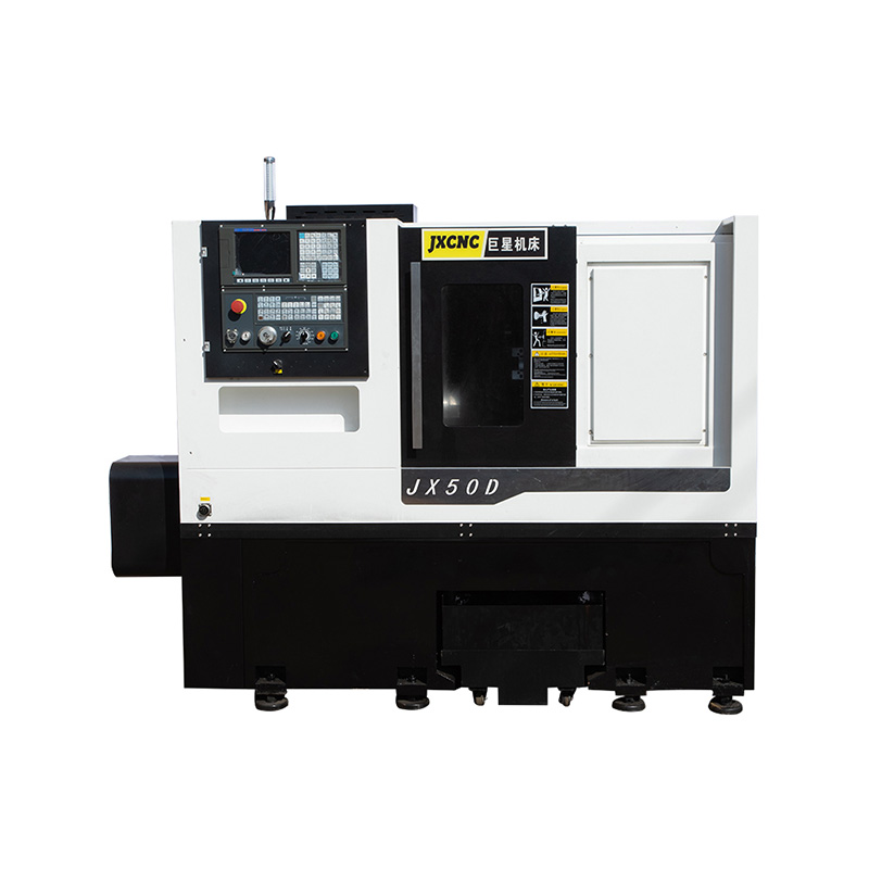
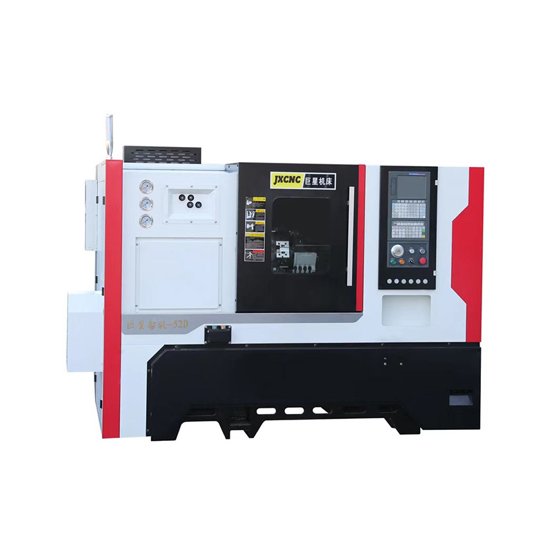
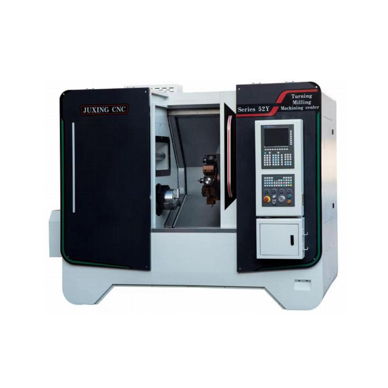
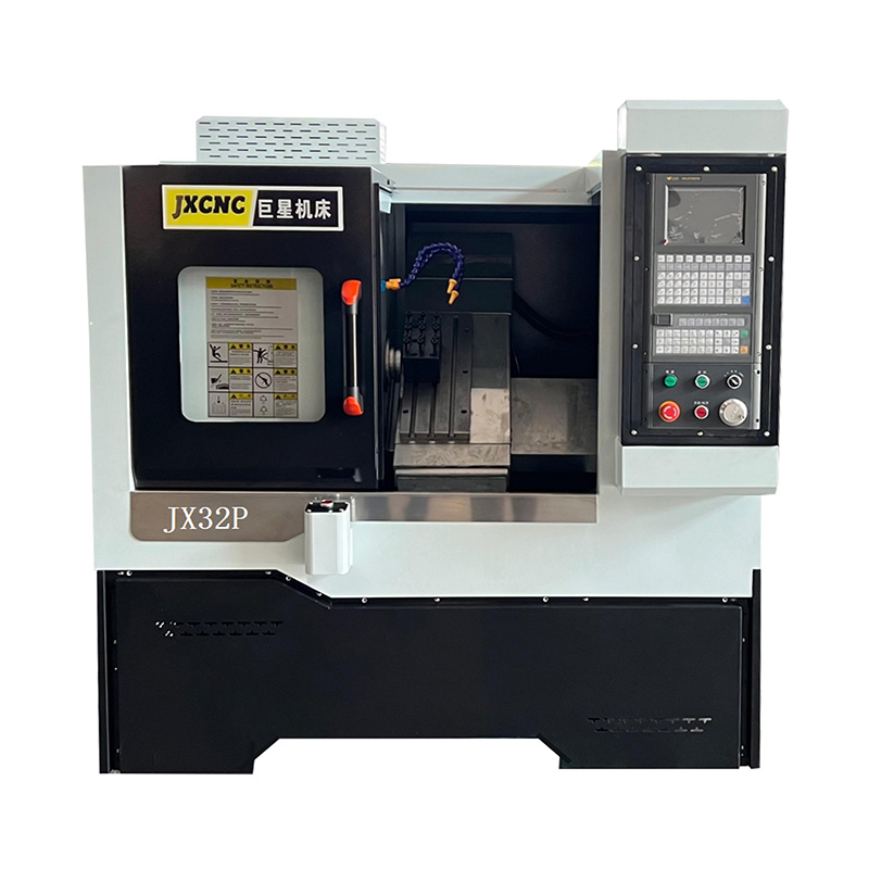
CNC fly cutting is often chosen for face finishing because of its simplicity and ability to create wide, continuous passes. Despite that advantage, surface irregularity can still appear, especially on larger workpieces or setups with marginal rigidity. The issue usually does not come from a single factor; instead, several mechanical and process-related influences interact during cutting.
A CNC Fly Cutter Machine relies on a single-point cutting action, meaning each revolution produces intermittent engagement rather than continuous chip removal. That pulsing cutting force can expose weaknesses in setup alignment, spindle stability, or tool geometry. Research and machining practice both show that surface finish problems often come from vibration, tool wear, and inconsistent cutting load rather than geometry alone.
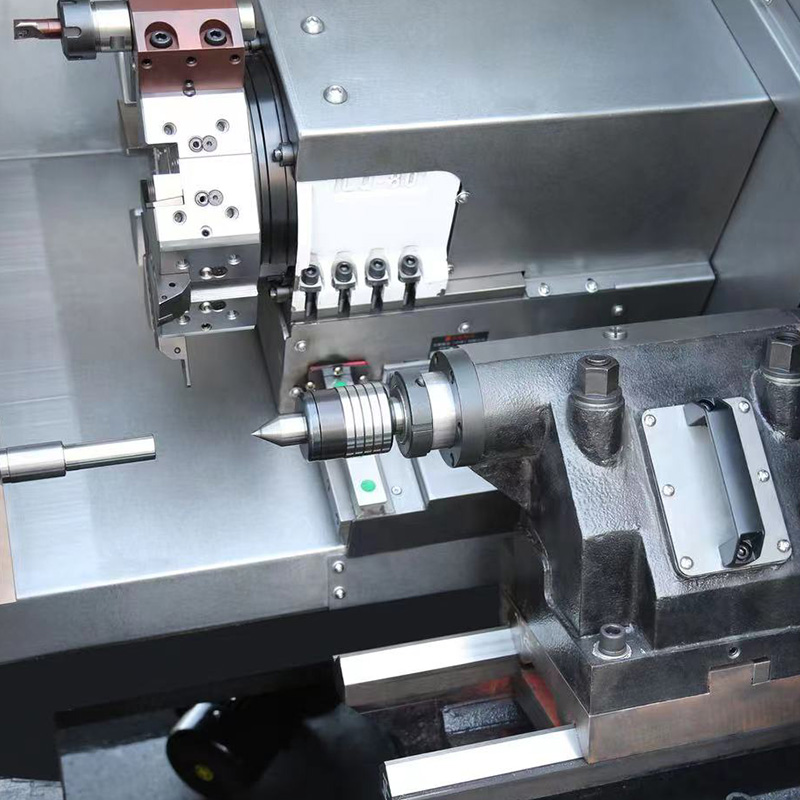
1. Intermittent Cutting Force Creates Surface Ripple Patterns
Fly cutters do not cut like multi-flute end mills. Each rotation produces a cycle of:
- Entry cut
- Peak chip load at center sweep
- Exit cut
This repeating force cycle can leave arc-shaped patterns across the surface. On machines with lower damping capacity or long tool reach, these patterns become more visible.
Even small spindle imbalance or toolholder eccentricity may amplify this effect, producing uneven “waves” instead of a flat face.
Typical symptoms include:
- Shallow arc marks across the workpiece
- Slight gloss variation between passes
- Repeating ripple spacing tied to feed rate
The pattern becomes more pronounced as feed per revolution increases or tool diameter grows.
2. Tool Geometry and Rake Angle Sensitivity
A fly cutter uses a single cutting insert or toolbit, so geometry matters more than in multi-tooth cutters.
Key parameters influencing finish:
- Rake angle influences chip flow and cutting resistance
- Clearance angle affects rubbing and heat buildup
- Tool projection distance changes stiffness behavior
- Cutting edge sharpness directly affects tearing vs shearing
Even a small deviation in tool height from spindle centerline can change cutting balance. A slightly low cutting edge may dig aggressively on one side of rotation and skim on the opposite side, creating uneven surface texture.
Reddit machining discussions often highlight this exact behavior: slight misalignment produces visible “backside roughness” due to uneven engagement across rotation.
3. Machine Rigidity and Vibration Response
A Linear Guide CNC Machine or knee mill with extended overhang reacts differently under fly cutting loads. Because the tool experiences alternating force instead of steady load, vibration risk increases.
Common rigidity-related contributors:
- Long tool stick-out amplifies deflection
- Weak spindle bearings allow micro-movement
- Fixture instability transmits vibration into workpiece
- Table resonance interacts with spindle frequency
Even small oscillations can imprint onto the final surface as repeating uneven bands.
On heavier industrial CNC platforms, damping is stronger, so the same fly cutter may produce a noticeably smoother finish.
4. Feed Rate vs Surface Scallop Formation
Surface texture is also governed by tool path spacing. Fly cutting produces overlapping circular tracks. The distance between those arcs determines visible scallop height.
A simplified relationship:
- Higher feed → wider arc spacing → rougher finish
- Lower feed → tighter overlap → smoother surface
Operators sometimes assume spindle speed is the main factor, but feed per revolution often dominates visible finish quality.
Material removal strategy also matters. A heavy single pass tends to amplify unevenness, while a light finishing pass stabilizes surface uniformity.
5. Tool Wear and Edge Condition Impact
Tool wear does not need to be severe to affect surface quality. Even micro-chipping on a single-point cutter can change how material shears.
Observed effects of wear include:
- Drag marks instead of clean shearing
- Localized tearing on softer metals
- Slight discoloration due to friction heat
- Irregular chip thickness across sweep
A worn fly cutter behaves inconsistently because every rotation relies on the same cutting edge. There is no redundancy like multi-flute tools provide.
6. Workpiece Material Behavior and Stress Release
Not all uneven surfaces originate from the machine. Material response plays a major role:
- Aluminum may smear under heat buildup
- Steel may spring slightly after clamping release
- Cast materials may contain density variation zones
Internal stress can cause subtle shape changes during machining. Once the top layer is removed, residual stress redistribution can slightly distort the face, making it appear uneven even though tool motion was stable.
This effect is more visible on long, thin, or pre-machined stock.
7. Spindle Alignment and Tramming Accuracy
Even small angular deviation between spindle axis and table surface introduces uneven cutting depth across the sweep.
A misaligned spindle produces:
- One side cutting deeper than the other
- Gradual taper across surface width
- Apparent “convex or concave” face after machining
This issue often gets misdiagnosed as tool quality or feed error, while actual root cause sits in machine setup geometry.
Routine tramming checks using dial indicators are essential for fly cutting consistency.
Practical Observation
Uneven surface finish from fly cutting typically originates from a combination of:
- Intermittent cutting dynamics
- Tool geometry sensitivity
- Machine rigidity limits
- Feed spacing selection
- Tool wear progression
- Material stress behavior
- Spindle alignment deviation
A CNC Fly Cutter Machine is highly effective for large surface finishing, yet it exposes mechanical imperfections more clearly than standard milling tools.



 English
 中文简体
中文简体 русский