English
 中文简体
中文简体 русский
CF40 Automatic CNC Polygon Turning Machine Lathe
Cat:Small Polygon Lathe
The CF40 Automatic CNC Polygon Turning Machine Lathe is specifically designed for small to medium-sized, high-precision parts milling, enabling the ma...
See Details
Lead time is calculated from order acknowledgment to shipment. Several measurable factors influence this duration.
Batch size and setup complexity: Setup time for a CNC lathe factory includes installing collets or chucks, loading tooling, setting work offsets, and proving out the first piece. For a simple part (diameter under 50 mm, length under 100 mm, tolerances ±0.1 mm), setup requires 30–90 minutes. For complex parts (multiple diameters, internal features, tolerances ±0.005 mm with specific surface finish requirements), setup takes 2–4 hours. Once running, cycle time per part ranges from 30 seconds (simple aluminum bushing) to 15 minutes (complex steel shaft with threading and grooving). For a batch of 500 parts with a 2-minute cycle time, machining time is 1,000 minutes (16.7 hours). Adding setup (2 hours), inspection (1 hour per 100 parts = 5 hours), and deburring/cleaning (0.5 hours per 100 parts = 2.5 hours) gives a total of approximately 26 hours of machine and labor time. Factory scheduling—typically 1–3 weeks of queue time before the job starts—then adds to lead time. A factory operating at 65% capacity quotes 2–3 weeks lead time for such a batch; at 85% capacity, lead time extends to 4–6 weeks.
Material availability: Standard round bar stock sizes (e.g., 12 mm, 20 mm, 30 mm diameter in 6061 aluminum, 12L14 steel, or 303 stainless) are typically stocked by the factory or available from local suppliers within 1–3 days. Non-standard diameters (e.g., 17.5 mm), specialty alloys (Inconel, titanium, Monel), or materials requiring certification (AMS, ASTM with traceability) have lead times of 5–15 days for material procurement. Factories that maintain an in-house material inventory of 50–100 common sizes can start production within 2 days of order receipt; those that order per job add 5–10 days to total lead time.
Secondary operations: Parts requiring operations beyond turning (e.g., milling flats, cross-drilling, heat treatment, plating, anodizing) need additional setup, often on different machines. A part that requires milling a hex feature on a CNC lathe with live tooling adds 10–30 seconds to cycle time but no extra setup. The same part sent to a separate milling machine adds 1–2 days of transfer and setup time. Heat treatment (case hardening to 50–55 HRC) adds 2–5 days including transport to an outside processor. Plating (zinc, nickel, or black oxide) adds 3–7 days. A factory with in-house secondary operations (milling, heat treat, and plating under one roof) reduces total lead time by 30–50% compared to subcontracting each step.
CNC lathe factories employ a hierarchical quality control system, with methods selected based on part complexity and tolerance requirements.
In-process controls: Modern CNC lathes incorporate tool touch-off probes that measure tool position before each job, setting tool length and diameter to ±0.002 mm accuracy. During production, some factories use parts probing—a touch probe mounted on the turret measures critical dimensions (diameter, length, thread position) after machining. For a shaft with a ±0.01 mm diameter tolerance, an in-process probe checks one part every 10–50 parts. If the measurement drifts by 0.005 mm from nominal, the control system automatically adjusts the tool wear compensation. This closed-loop feedback keeps production within tolerance without operator intervention. Factories using in-process probing report defect rates of 0.5–1.5% compared to 2–5% for factories relying on periodic manual checks.
Post-process inspection methods:
Hand gauges (calipers, micrometers, thread gauges): Used for tolerances of ±0.02 mm or looser. A micrometer reads to 0.001 mm, but operator technique yields repeatability of ±0.002–0.005 mm. For batches under 100 parts, hand gauges are efficient; for batches above 500 parts, they are replaced by automated methods.
Optical comparators: Project a magnified silhouette of the part onto a screen. Used for measuring radii, angles, and contours that are difficult to gauge mechanically. Measurement accuracy: ±0.005 mm for features up to 100 mm in length. Typical inspection time per part: 2–5 minutes for 5–10 features.
Coordinate measuring machines (CMMs): Contact or non-contact systems that probe multiple points on the part. A bridge CMM with a touch probe achieves accuracy of ±0.001–0.003 mm over a 200 mm measurement volume. Inspection time per part: 3–10 minutes for 20–50 features. Factories running ISO 9001 or AS9100 systems may require CMM inspection of the first article and then one part per shift or per 100 parts.
Surface finish testers: A stylus drawn across the part surface measures Ra (average roughness), Rz (peak-to-valley height), and other parameters. Typical tolerance for turned surfaces: Ra 0.8–3.2 µm. A contact profilometer with 5 µm stylus tip radius provides measurement repeatability of ±0.05 µm Ra.
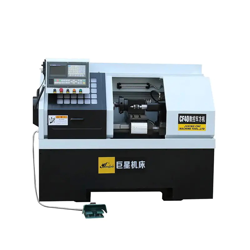
The CF40 Automatic CNC Polygon Turning Machine Lathe is specifically designed for small to medium-sized, high-precision parts milling, enabling the ma...
See Details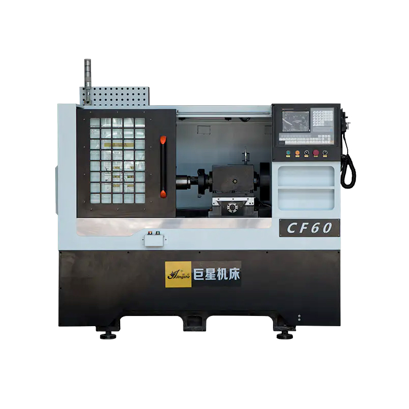
The CF60 CNC Polygon Lathe is a highly efficient and versatile machine tool designed for small to medium-sized precision parts milling. It is capable ...
See Details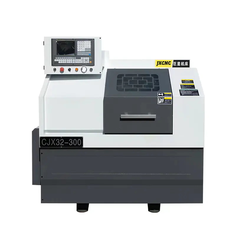
The JX32-300 Mini Economical CNC Lathe Machine is designed to provide high precision and efficient machining for a wide range of metal products. With ...
See Details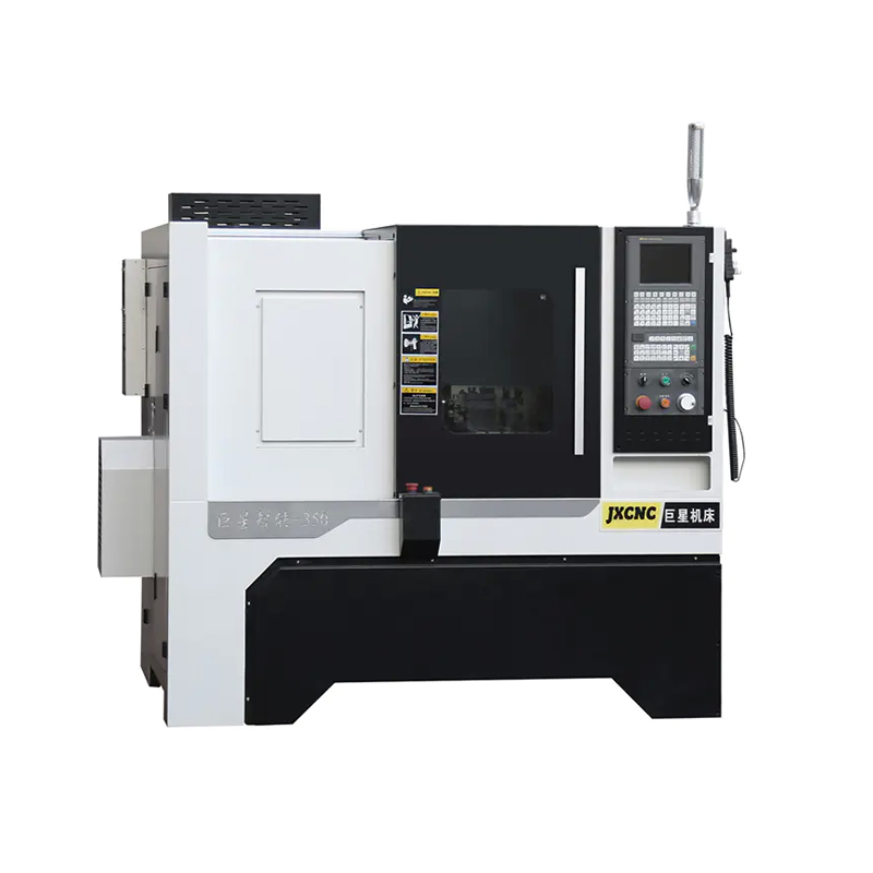
The JX350 Gang Type CNC Lathe for Cutting Tool with Rapid Tool Changing is designed to deliver high precision and efficiency in cutting tool operation...
See Details
Introducing the JX36P China Good Supplier CNC Lathe Machine, a high-quality and efficient tool designed for precision machining. With its horizontal i...
See Details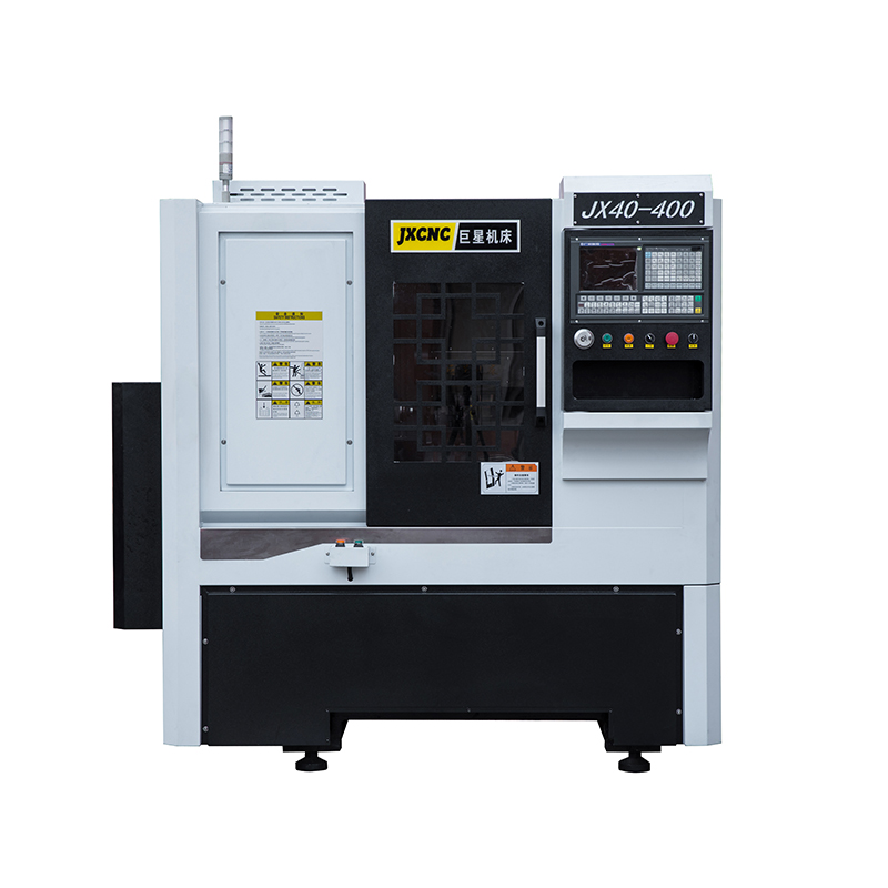
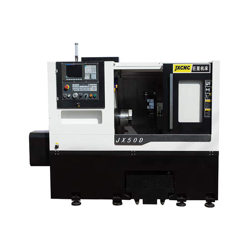
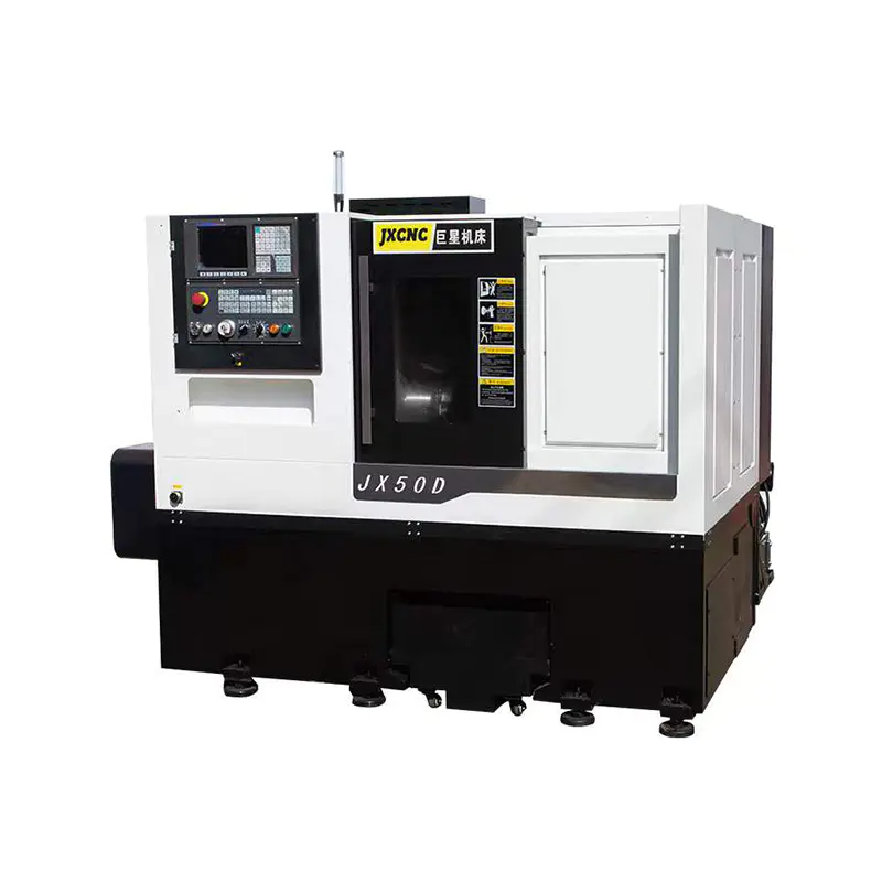
The JX40-400 Factory High Speed Precision CNC Lathes are designed to provide exceptional efficiency and accuracy in machining processes. With the abil...
See Details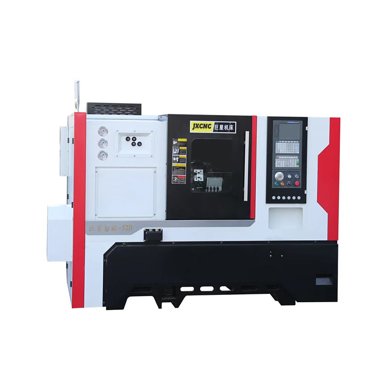
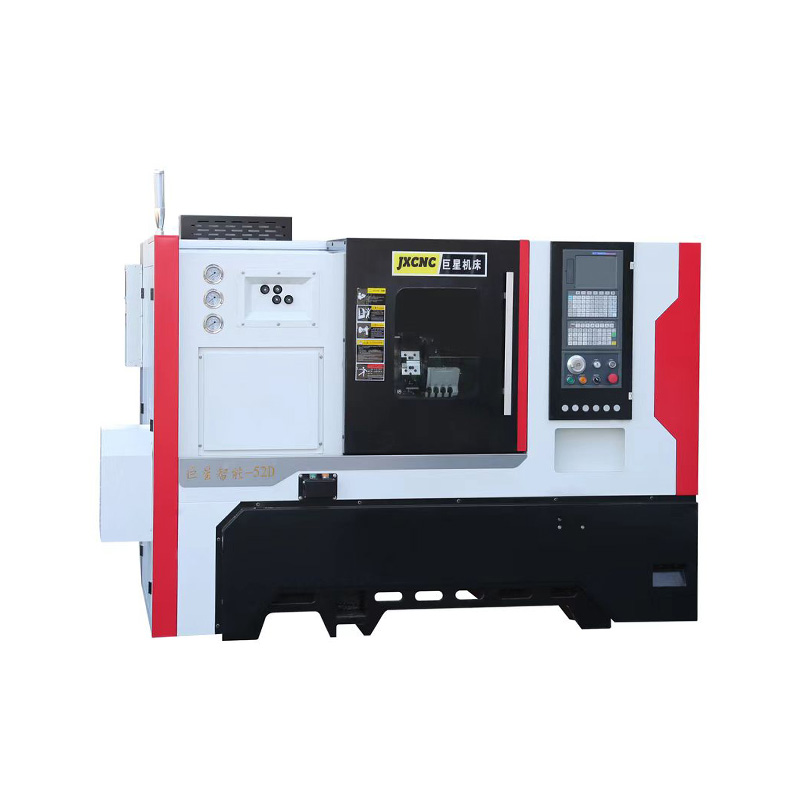
As a trusted machine tool equipment supplier in China, we prioritize customer satisfaction and strive to provide the solutions and support. Our JX52D ...
See Details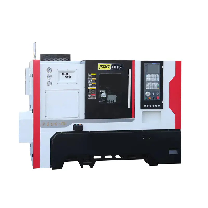
The JX52D Machine Tool CNC Lathe is specifically designed for lathe every kinds of material with precision and efficiency. It is equipped with advance...
See DetailsTEL : +86-576-87491531
FAX : +86-576-87493038
E-MAIL : chinajuxing@aliyun.com
ADDRESS: Longxi Industrial Zone, Yuhuan City, Taizhou City, Zhejiang Province, China
CopyrightTaizhou Yestar Intelligent Equipment Co., Ltd. All Rights Reserved.