English
 中文简体
中文简体 русский
CF32 Hydraulic Clamping CNC Polygon Turning Machine
Cat:Small Polygon Lathe
CF32 hydraulic clamping CNC polygon lathe is designed for milling small and medium-sized high-precision parts, which can mill square, octagonal, hexag...
See Details
Producing hexagonal shafts, square drive ends, or multi-sided connector profiles on a conventional lathe is not straightforward — it typically means transferring the part to a milling machine, setting up a second fixture, running a separate operation, and then dealing with the tolerance stack that comes from two separate setups. For manufacturers producing these shapes in volume, that process adds time, cost, and dimensional inconsistency that shows up as rejects or assembly problems downstream. A CNC Polygon Lathe addresses this directly by generating polygon cross-sections within a single turning operation, eliminating the secondary process entirely.
Conventional turning produces round parts. The workpiece rotates, the cutting tool feeds, and the result is a cylinder. Producing a hexagon, square, or other polygon from a round blank on a conventional lathe requires either using the lathe purely for the cylindrical portions and sending the part elsewhere for the polygon features, or giving up the lathe entirely and using milling from the start.
Neither approach is efficient for high-volume production of shaft components with both cylindrical and polygonal features. The multiple setups introduce cumulative positioning error and increase cycle time with every part.
A CNC Polygon Lathe produces polygon cross-sections by synchronizing the rotation of the cutting tool head with the rotation of the workpiece spindle at a precise speed ratio. The workpiece rotates continuously, and the tool head — carrying multiple cutting inserts arranged radially — also rotates, but at a speed ratio that determines the number of sides in the resulting polygon.
When this synchronization is maintained precisely throughout the cut, each insert removes material at a defined angular position relative to the workpiece, and the combined effect of all inserts cutting in sequence produces a polygon shape rather than a circle. The relationship between tool rotation speed, workpiece rotation speed, and the number of inserts determines the number of sides in the output geometry.
This is fundamentally different from milling, where the workpiece is stationary and the tool path traces the polygon outline. In polygon turning, both the workpiece and the tool are rotating simultaneously, and the polygon emerges from the synchronized interaction between them.
When a part requires both round and polygon features — a shaft with a hexagonal drive end and cylindrical bearing journals, for example — the conventional approach involves at least two separate machine setups. Each setup introduces its own positioning error, and those errors add together in the finished part.
The practical consequences include:
For parts where the concentricity between the polygon and cylindrical sections is a functional requirement — drive shafts, fastener blanks, connector bodies — this error accumulation is not just an efficiency problem. It is a quality problem.
Milling can produce accurate polygon shapes, but it is not a fast process for high-volume shaft production. The tool path for milling a hexagonal section requires multiple passes, and the interrupted cutting of each flat face generates vibration that can affect surface finish and tool life. Setup time per part is higher, and the process does not integrate as smoothly with bar-fed automatic production as turning-based operations do.
For manufacturers running high volumes of standard polygon shapes, milling is a workable but inefficient solution compared to what synchronized polygon turning can achieve.
The polygon produced by a CNC Polygon Lathe is determined by the ratio between tool rotation speed and workpiece rotation speed, combined with the number of cutting inserts in the tool head.
A simple relationship governs the output:
This means the same machine can produce different polygon shapes by changing the speed ratio in the CNC program and, where necessary, changing the tool head configuration. The flexibility to switch between polygon geometries without a complete machine changeover is one of the practical advantages over dedicated milling setups for each shape.
In manual or older mechanical polygon turning equipment, maintaining precise synchronization across the full length of a polygon feature was a significant challenge. Any variation in the speed ratio produced geometry errors along the length of the cut.
CNC control resolves this by continuously monitoring and correcting the relationship between spindle and tool head throughout the cut. The result is consistent polygon geometry from one end of the feature to the other, and consistent geometry from one part to the next across a production run.
Because the polygon feature is generated in the same setup as the surrounding cylindrical features, the concentricity between them is determined by the machine's positioning accuracy rather than by the accumulated error of multiple setups. For precision shaft components where the polygon and cylindrical sections must be concentric within tight tolerances, this is a significant quality improvement over the conventional multi-operation approach.
The time saving from eliminating a secondary milling operation compounds significantly at production scale. Consider the components of the conventional process that polygon turning removes:
Each of these consumes time per part. At volumes of hundreds or thousands of parts per shift, the accumulated time saving from eliminating the secondary process is substantial.
CNC synchronization maintains the same speed ratio and cutting geometry across every part in a run. The polygon geometry produced on part one is the same as on part one thousand, assuming consistent material and cutting tool condition. This run-to-run consistency supports quality targets in industries where part interchangeability is a requirement.
Not every part with a polygon feature is a good fit for CNC polygon turning. The process is most effective for:
The process is less suited to one-off or very low-volume work, where the setup time and programming effort are not justified by the quantity.
Several manufacturing sectors produce the types of components that CNC polygon turning handles well:
| Characteristic | CNC Polygon Lathe | Conventional Lathe Plus Milling | Dedicated Milling Center |
|---|---|---|---|
| Number of setups for polygon plus cylindrical | One | Two or more | One or more |
| Concentricity control | High — single setup | Limited — multi-setup error accumulation | Depends on setup |
| Cycle time for high-volume production | Short — integrated operation | Longer — sequential operations | Longer — tool path based |
| Geometry flexibility | High — speed ratio adjustment | Limited by milling setup | High but slower |
| Bar feed integration | Yes — compatible with turning cell | Partial — requires transfer | Limited |
| Capital cost | Moderate | Lower per machine, higher total | Higher |
| Operator requirement | Lower — automated synchronization | Higher — multiple setup operations | Moderate |
The table reflects general tendencies rather than absolute values — specific machines and configurations vary. The key message is that the single-setup nature of polygon turning addresses the root cause of the multi-operation quality and efficiency problems rather than managing their consequences.
The first question is whether the polygon geometries needed for the production parts fall within the machine's capability range. This includes the range of polygon sizes, the depth of cut required to reach the finished polygon dimension from the bar stock diameter, and whether the part requires polygon features at one end or at multiple locations along the shaft.
A CNC Polygon Lathe integrated with bar feeding and parts collection automation runs more continuously and requires less operator intervention than a standalone machine loaded part by part. For high-volume applications, the economics of automation are usually straightforward — more parts per shift and lower labor cost per part.
The machine's control system compatibility with other equipment in the production cell also matters for data collection, process monitoring, and quality management.
The polygon tool head — the rotating cutter assembly — needs to be designed for the polygon geometry being produced. Some machines support quick-change tool heads that allow switching between different polygon geometries without lengthy changeover. For manufacturers producing a range of polygon shapes, this flexibility reduces downtime between product runs.
Polygon turning involves more complex setup and programming than standard cylindrical turning. Supplier support for initial installation, process setup, and ongoing application troubleshooting is a practical consideration in the machine selection process, particularly for manufacturers introducing this technology for the first time.
Polygon machining problems — inconsistent concentricity, high cycle times from multiple setups, quality issues traced back to the secondary milling operation — are addressable at the process level rather than the quality-management level. A CNC Polygon Lathe moves the polygon feature into the primary turning operation, where it benefits from the same setup, the same datum references, and the same process control as the cylindrical features alongside it. The result is a more efficient production flow and a more consistent part. Taizhou Yestar Intelligent Equipment Co., Ltd. manufactures CNC Polygon Lathe equipment for precision shaft and component machining applications, working with manufacturers on machine configuration, polygon geometry requirements, and production cell integration. If you are evaluating equipment for a polygon machining application or looking to bring a secondary milling operation back into a single-setup turning process, reaching out to their technical team is a practical next step.
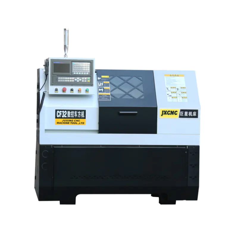
CF32 hydraulic clamping CNC polygon lathe is designed for milling small and medium-sized high-precision parts, which can mill square, octagonal, hexag...
See Details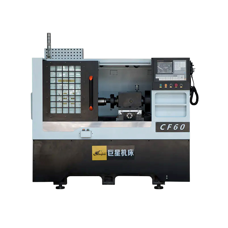
The CF60 CNC Polygon Lathe is a highly efficient and versatile machine tool designed for small to medium-sized precision parts milling. It is capable ...
See Details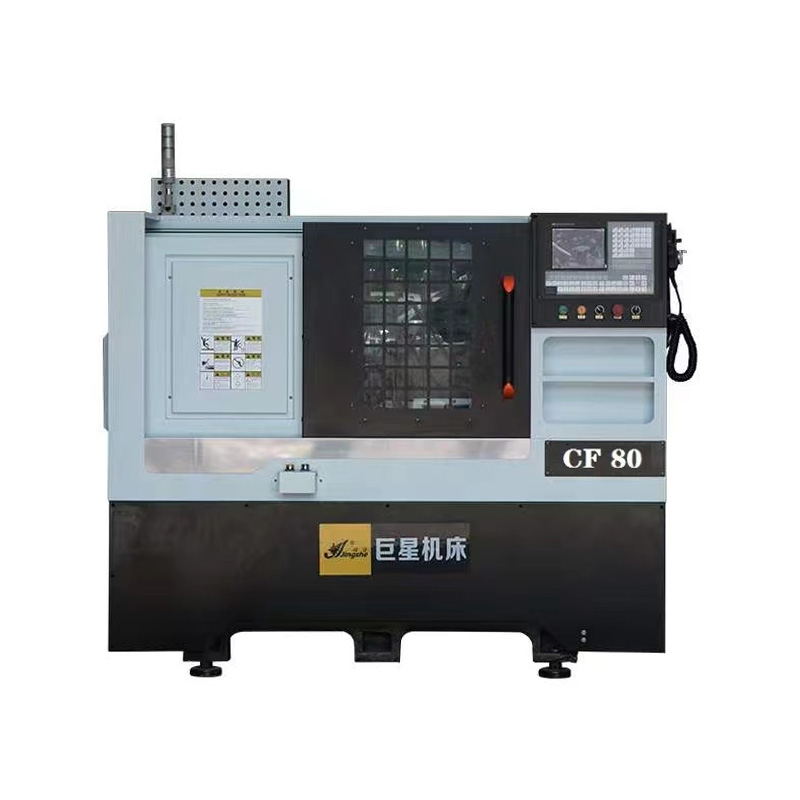
Introducing the CF80 Auto Polygon Lathe Hexagonal Tailstock Lathe Machine. This machine is specifically designed for the production of medium and smal...
See Details
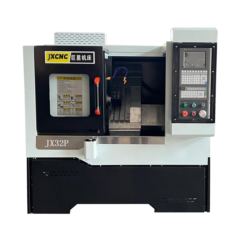
Introducing the JX36P China Good Supplier CNC Lathe Machine, a high-quality and efficient tool designed for precision machining. With its horizontal i...
See Details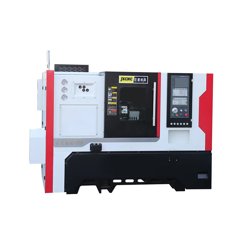
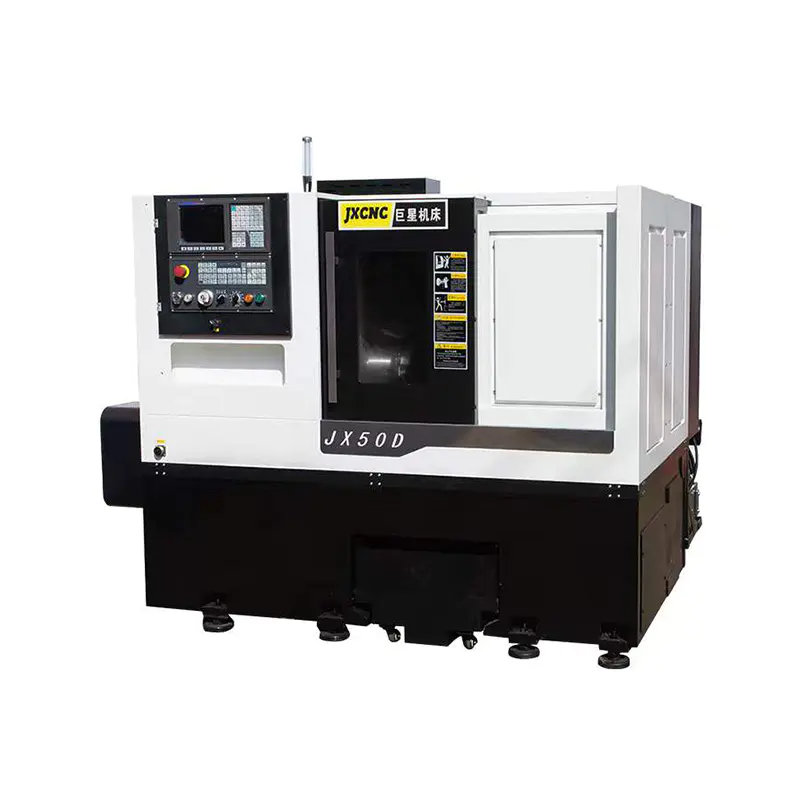
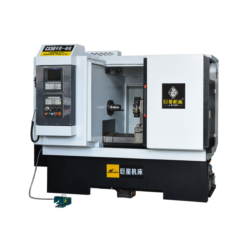
As a trusted machine tool equipment supplier in China, we prioritize customer satisfaction and strive to provide the solutions and support. Our JX52D ...
See Details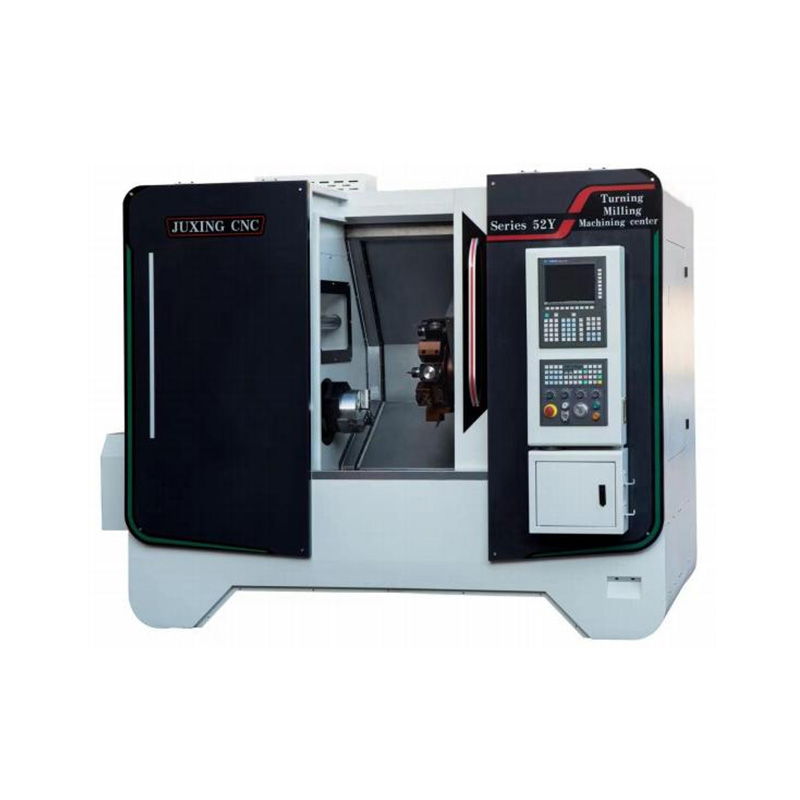
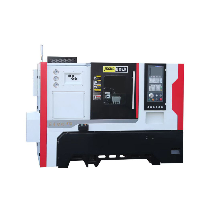
In conclusion, the JX52Y CNC Turning Lathes with Computer Control System is a highly advanced and efficient machine that combines the functionality of...
See Details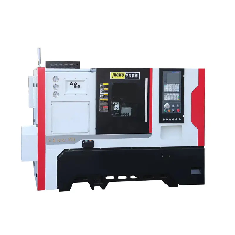
The JX52D Machine Tool CNC Lathe is specifically designed for lathe every kinds of material with precision and efficiency. It is equipped with advance...
See DetailsTEL : +86-576-87491531
FAX : +86-576-87493038
E-MAIL : chinajuxing@aliyun.com
ADDRESS: Longxi Industrial Zone, Yuhuan City, Taizhou City, Zhejiang Province, China
CopyrightTaizhou Yestar Intelligent Equipment Co., Ltd. All Rights Reserved.