English
 中文简体
中文简体 русский
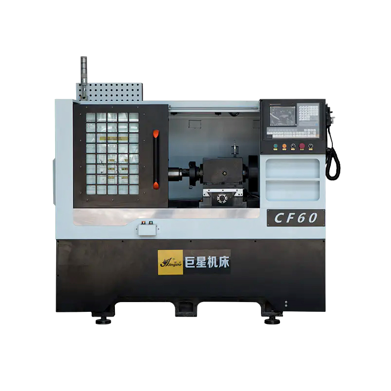
CF60 CNC Polygon Lathe
Cat:High Rigidity Polygon Lathe
The CF60 CNC Polygon Lathe is a highly efficient and versatile machine tool designed for small to medium-sized precision parts milling. It is capable ...
See Details
Face milling for flat surface generation.
CNC milling machines factory use rotating multi-tooth cutters to remove material from a workpiece. Face milling is the process of creating a flat surface perpendicular to the spindle axis. A face mill with indexable carbide inserts (diameter 50–160 mm) rotates at 800–4,000 rpm, depending on material. For aluminum 6061, a typical face milling operation runs at 3,000 rpm with a feed rate of 500–800 mm/min, removing 2–3 mm depth per pass. The resulting surface flatness ranges from 0.01 to 0.05 mm over a 300 mm length, depending on machine rigidity and cutter condition. Face milling is used on engine block decks, fixture plates, and machine tool bases. The operation preferentially uses a cutter diameter larger than the workpiece width so that the entire surface is cut in one pass, avoiding step lines between adjacent passes. When the workpiece width exceeds the cutter diameter, adjacent passes overlap by 30–50% of the cutter width to maintain uniform surface texture.
Peripheral milling for contour and profile creation.
Peripheral milling—also called slab or end milling—removes material using the side of a cylindrical cutter. This method cuts vertical walls, slots, and complex 2D contours. An end mill (2–25 mm diameter) with four flutes operates at spindle speeds of 4,000–15,000 rpm for aluminum and 800–4,000 rpm for steel. The depth of cut per pass ranges from 0.5 mm (for hardened steels above 40 HRC) to 8 mm (for aluminum). Peripheral milling generates heat at the tool-workpiece interface; coolant (water-soluble oil, 5–8% concentration) reduces cutting zone temperature from approximately 400–600°C to 150–250°C, extending tool life by 3–5 times. A 10 mm end mill cutting 4140 steel at 1,000 rpm, 200 mm/min feed, and 2 mm depth of cut will produce 20–40 parts per insert edge before wear reaches 0.2 mm flank wear—the typical replacement criterion. For comparison, dry cutting under the same conditions yields 5–10 parts per edge.
Drilling and hole-making cycles in CNC milling.
Although a drill press may be more efficient for single holes, CNC milling machines perform drilling operations within the same setup as milling features. Standard canned cycles (G81 for drilling, G83 for peck drilling) automate the drilling sequence. A G83 peck drilling cycle for a 10 mm diameter hole in stainless steel (depth 50 mm) might retract the drill after every 5 mm of advance to clear chips and flood coolant into the hole. This pecking reduces tool breakage by 60–80% compared to continuous drilling. Positional accuracy of holes drilled on a CNC mill is ±0.01–0.03 mm for center distances up to 300 mm, provided the machine undergoes annual ballbar calibration. Tapping cycles (G84) for threaded holes use a rigid tap holder synchronized to spindle rotation; a 1/4-20 tap in aluminum at 500 rpm produces threads within a 2H class fit. Without rigid tapping, a floating tap holder allows axial movement to compensate for synchronization errors, reducing thread accuracy to 3H class.
3D contouring with ball-nose end mills.
Three-dimensional surfaces—molds for injection molding, dies for stamping, and aerospace components—require ball-nose end mills. These cutters have a hemispherical tip with a radius equal to half the tool diameter. For a 6 mm ball-nose mill, the stepover between adjacent tool paths (the scallop height) determines surface finish. A stepover of 0.3 mm (5% of tool diameter) produces a theoretical scallop height of approximately 0.002 mm—smooth enough for most mold applications without hand polishing. Cutting speed for a ball-nose end mill in tool steel (P20, 30 HRC) is 150–250 m/min, which at 6 mm diameter translates to 8,000–13,000 rpm. The feed per tooth is reduced to 0.02–0.05 mm because the cutting speed approaches zero at the tool tip. Total machining time for a 3D surface measuring 200 × 200 mm with a 0.3 mm stepover and 0.2 mm depth of cut is typically 2–6 hours, depending on surface complexity and machine acceleration capabilities (0.5–1.5 g).
Three-axis vs. multi-axis CNC milling configurations.
A standard three-axis CNC milling machine moves the spindle in X (left-right), Y (front-back), and Z (up-down) directions. The workpiece remains stationary on a table. This configuration machines 85–90% of prismatic parts—those with features accessible from one direction, such as engine blocks, valve bodies, and mounting plates. Adding a fourth axis (A-axis) rotates the workpiece about the X-axis, allowing machining of four sides in one setup. A part requiring holes on both the top and front face, for example, can be fixtured once and indexed 90 degrees, eliminating a second setup and reducing positional error from ±0.05 mm (two setups) to ±0.01 mm (one setup). Five-axis machining adds a rotary B-axis (about the Y-axis) or tilting spindle. With five axes, a part like an impeller (blades with undercuts) is machined in one setup, whereas three-axis milling would require 5–8 separate fixtures and setups, each introducing geometric error.
Spindle speed, feed rate, and depth of cut relationships.
Three parameters govern the material removal rate (MRR). MRR = depth of cut × width of cut × feed rate. For a given material and tool diameter, increasing any parameter raises MRR but also increases cutting forces and heat. The spindle speed determines the surface speed at the cutter periphery. For a 12 mm end mill in 6061 aluminum, the manufacturer’s recommended surface speed is 400–600 m/min. Using 500 m/min, spindle speed = (500 × 1000) / (π × 12) = 13,260 rpm. Feed rate is then calculated as feed per tooth (0.05–0.15 mm for aluminum) × number of flutes (4) × spindle speed. At 0.10 mm per tooth: feed rate = 0.10 × 4 × 13,260 = 5,304 mm/min. Depth of cut for roughing is 1.5–2× tool diameter (18–24 mm) for aluminum; for finishing, 0.2–0.5 mm. Exceeding these values by 20% increases tool wear by 50–100%. For steel (4140, 30 HRC), surface speed drops to 80–120 m/min. The same 12 mm end mill runs at 2,400 rpm (using 90 m/min). Feed per tooth reduces to 0.03–0.08 mm, giving a feed rate of 0.05 × 4 × 2,400 = 480 mm/min. Depth of cut is 2–6 mm for roughing. The MRR for aluminum (5,304 × 12 × 3 mm typical) is 191,000 mm³/min; for steel (480 × 12 × 3 mm) it is 17,300 mm³/min—an 11-fold difference, reflecting the lower machinability of steel.
Workholding methods and their effect on accuracy.
The way a workpiece is secured influences achievable tolerances. Common workholding methods include:
Vise (mechanical or hydraulic): Suitable for rectangular blocks. Clamping force ranges from 5 to 20 kN. Parallels under the workpiece ensure the top surface is parallel to the machine table within 0.01–0.03 mm. Vises induce workpiece deformation if clamping pressure is too high; a 100 mm long aluminum block compressed by 10 kN force shortens by 0.02–0.05 mm elastically. When unclamped, this elastic recovery changes finished dimensions by the same amount. Using a torque wrench set to 20–25 Nm on the vise handle standardizes clamping force.
Fixture plate with toe clamps: For irregular shapes or large workpieces (over 300 mm in any dimension). Clamps apply downward force at 3–6 points. Fixture plates have grid patterns of threaded holes (M8–M16) on 25–50 mm spacing. The flatness of the fixture plate (typically ground to 0.02 mm over its area) transfers to the workpiece. Toe clamps generate 3–8 kN each; using four clamps distributes the total force evenly.
Vacuum chuck: For thin, flat parts (thickness under 6 mm) that cannot be clamped. Vacuum pressure of 60–80 kPa (0.6–0.8 bar below atmospheric) provides holding force of 30–40 kN per square meter. A 200 × 200 mm part receives 1,200–1,600 N total clamping force—sufficient for light milling (0.5–2 mm depth of cut) but not for heavy material removal. Vacuum chucks require a smooth, undampered part back surface; holes or rough cast surfaces leak vacuum, reducing holding force by 60–90%.
The CF60 CNC Polygon Lathe is a highly efficient and versatile machine tool designed for small to medium-sized precision parts milling. It is capable ...
See Details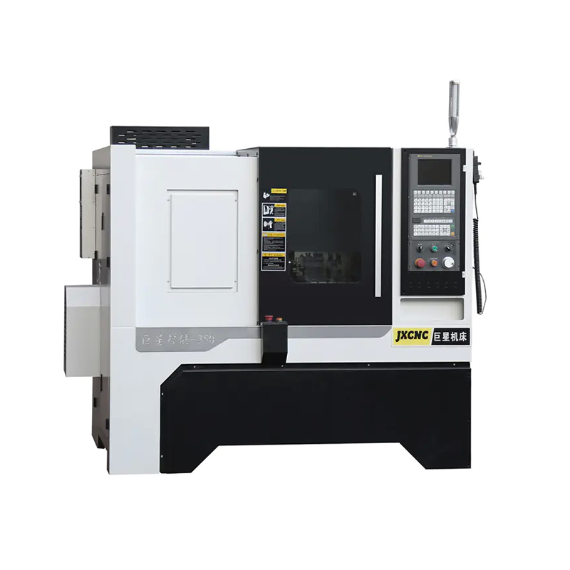
The JX350 Gang Type CNC Lathe for Cutting Tool with Rapid Tool Changing is designed to deliver high precision and efficiency in cutting tool operation...
See Details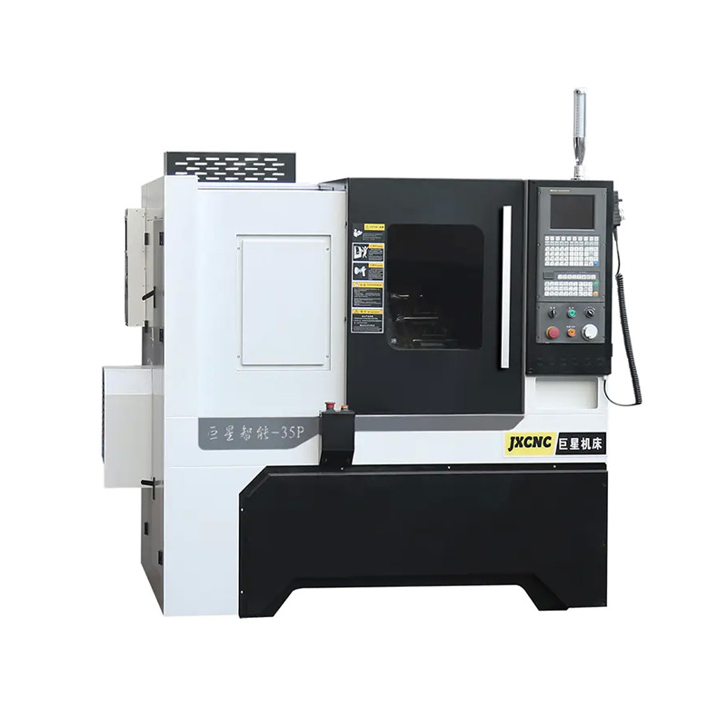
The JX35P CNC Hiwin Linear Guide Machine with High Precision is a reliable and robust solution for various machining applications. With its horizontal...
See Details
Introducing the JX36P China Good Supplier CNC Lathe Machine, a high-quality and efficient tool designed for precision machining. With its horizontal i...
See Details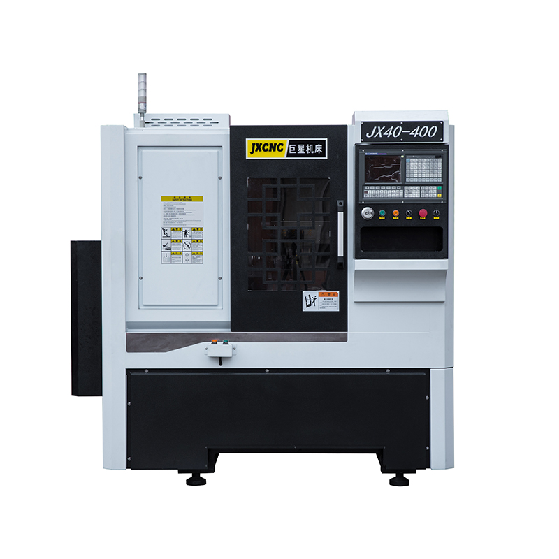
The JX40-400 Factory High Speed Precision CNC Lathes are designed to provide exceptional efficiency and accuracy in machining processes. With the abil...
See Details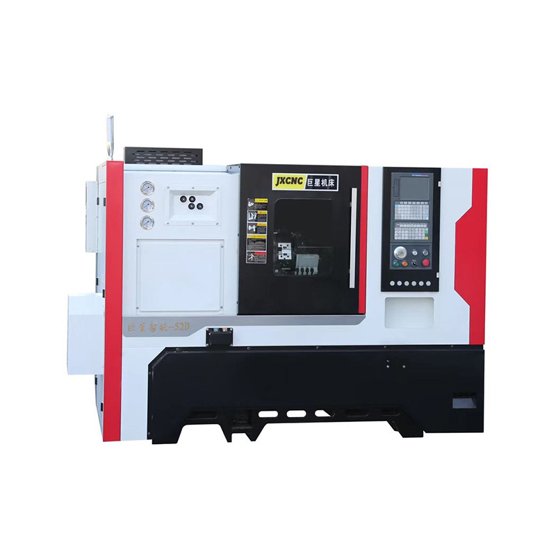
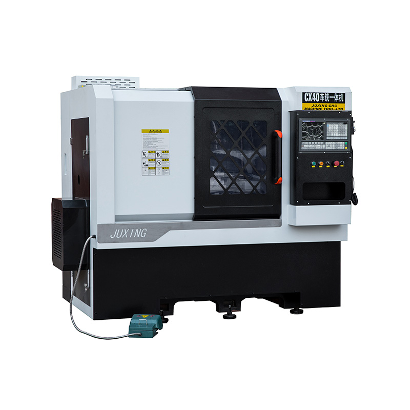
As a trusted machine tool equipment supplier in China, we prioritize customer satisfaction and strive to provide the solutions and support. Our JX52D ...
See Details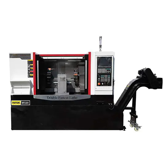
The JX125 Double Head CNC Machine is a cutting-edge machine tool that utilizes a central spindle, two Z-axes, two X-axes, and bidirectional drag plate...
See Details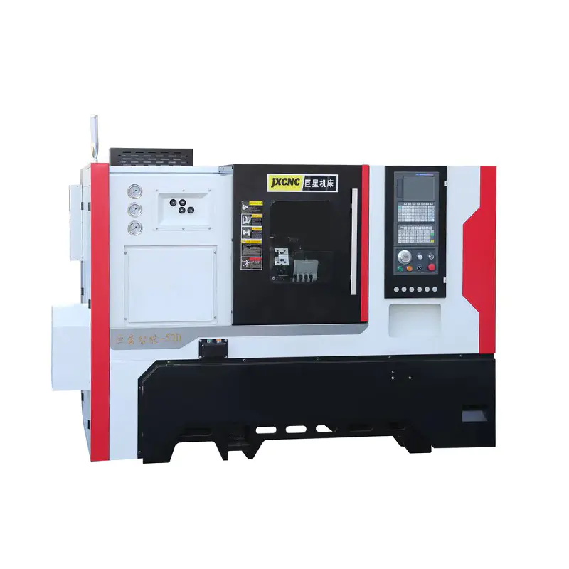
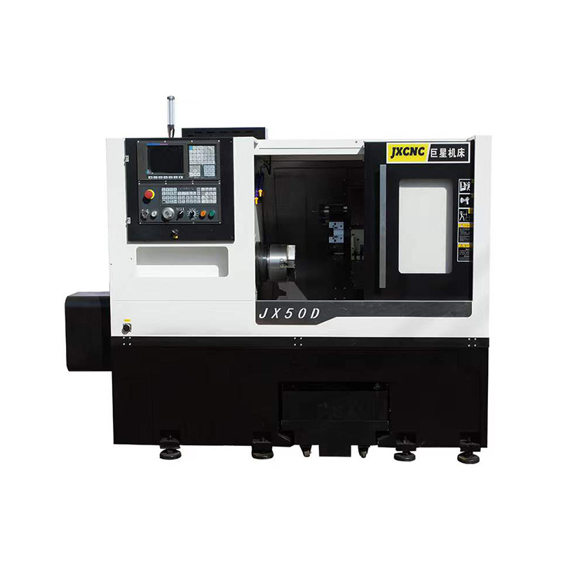
The JX52D Machine Tool CNC Lathe is specifically designed for lathe every kinds of material with precision and efficiency. It is equipped with advance...
See DetailsTEL : +86-576-87491531
FAX : +86-576-87493038
E-MAIL : chinajuxing@aliyun.com
ADDRESS: Longxi Industrial Zone, Yuhuan City, Taizhou City, Zhejiang Province, China
CopyrightTaizhou Yestar Intelligent Equipment Co., Ltd. All Rights Reserved.